


Faraday's Law and Lenz's Law
Induced EMF in a rotating coil
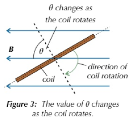
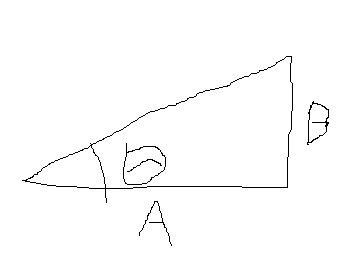
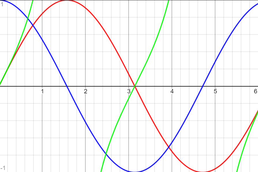
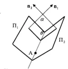
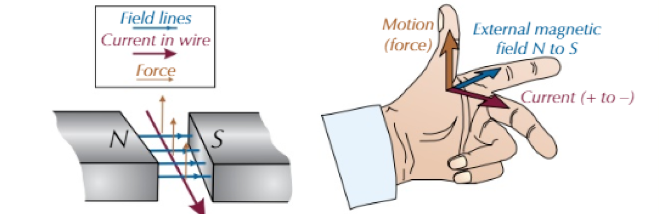
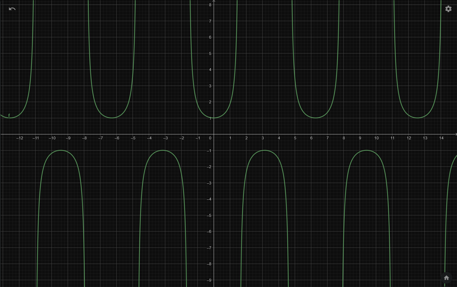
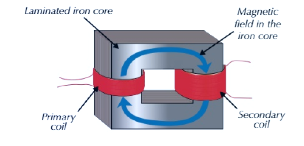
- When a coil such as that in Figure 3 rotates uniformly (at a steady speed) in a magnetic field, the coil cuts the flux and an alternating e.m.f. is induced.
- The amount of flux cut by the coil (flux linkage) is given by:
- \(N\phi = BAN\cos\theta\).
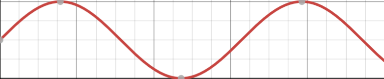
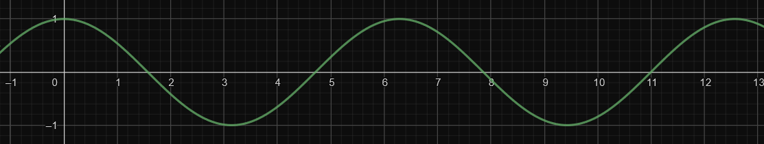
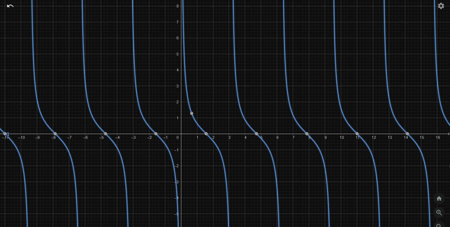
- As the coil rotates, \(\theta\) changes so the flux linkage varies sinusoidally between \(+BAN\) and \(-BAN\).
- How fast \(\theta\) changes depends on the angular speed \(\omega\) of the coil \(\theta=\omega t\)
- \(N\phi=BAN\cos\omega t\)
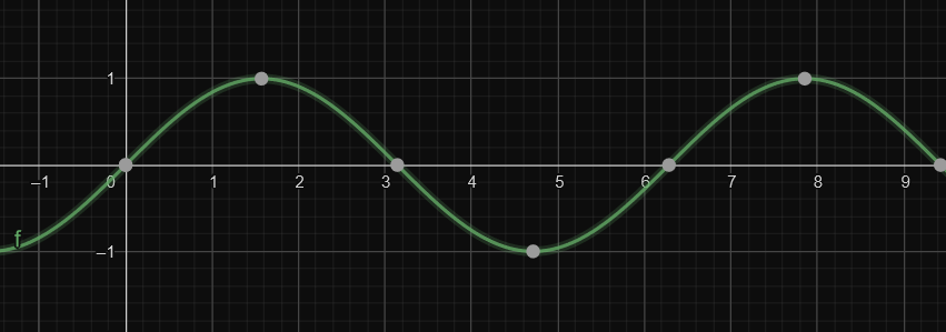
- The induced emf depends on the rate of change of flux linkage (Faraday's Law) so it also varies sinusoidally.
- The equation for emf at time=\(t\) is: \(\varepsilon=BAN\omega \sin\omega t\)

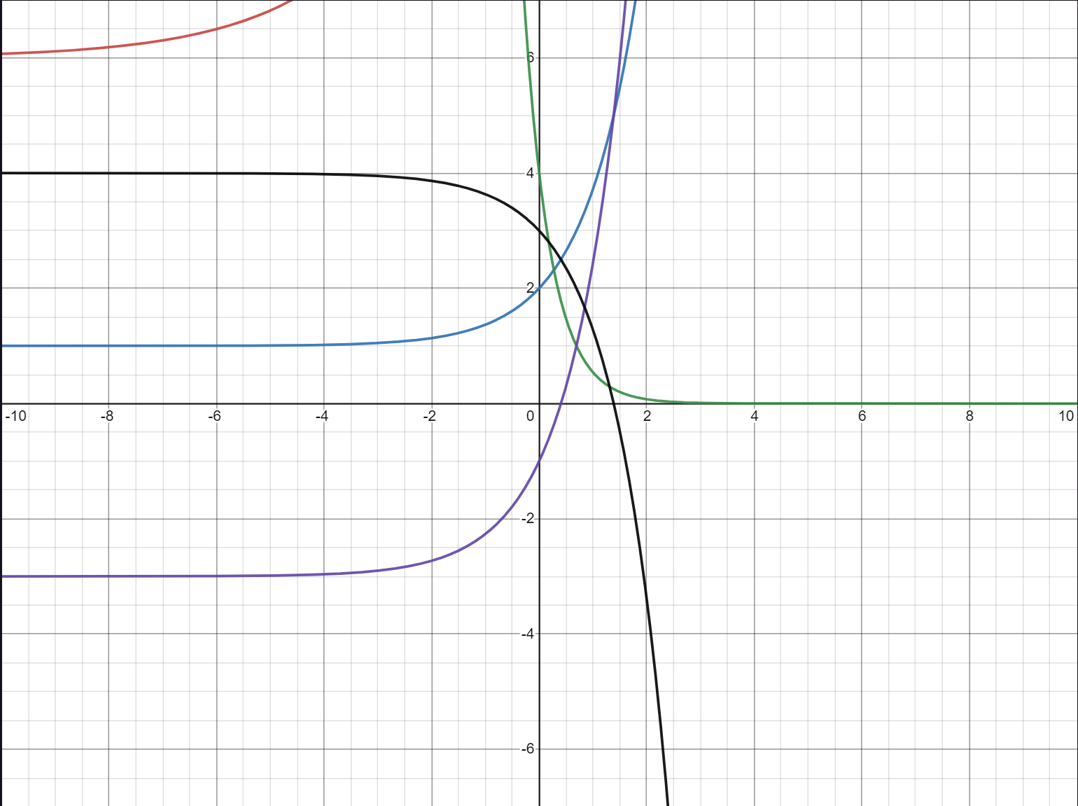
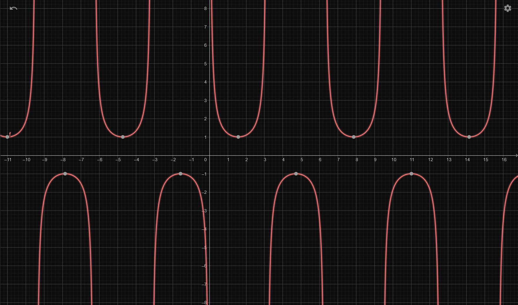
The shape of the graph of induced e.m.f. can be altered by changing the speed of rotation or the size of the magnetic field:
- Increasing the speed of rotation will increase the frequency and increase the maximum e.m.f.
- Increasing the magnetic flux density \(B\) will increase the maximum e.m.f., but will have no effect on the frequency.
Summary
- AC electricity alternates sinusoidally with a frequency of 50hz and a peak potential difference of 325 volts.
- An oscilloscope trace can be used to analyse a wave and measure the time period and peak potential difference.
- The root mean squared of both current and potential difference can be used to calculate the power rating of an AC supply.