


Fetch Decode Execute Cycle
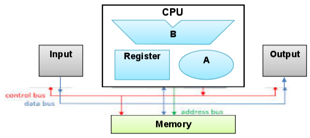
- The Central Processing Unit (CPU) is the brain of the computer.
- It is the component that does all of the clever calculations.
- It reads the instructions in a program, decides what to do about each instruction and then sends out signals to all of the different pieces of hardware to make things happen.
- This is quite a complicated idea so we need to produce a model (an abstraction) that we can start working with.
- Programs are simply sets of instructions that a programmer has written.
- When you want to 'run' a program, you might double-click on it in a computer system to 'open' it.
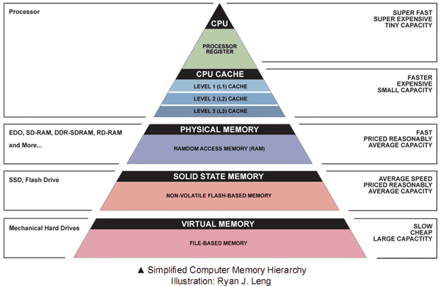
- When we double-click on it, we are sending an instruction to the operating system to go and find the program on the hard drive, copy it and put the copy in RAM.
a) To 'run' a program, the CPU has to get the first instruction in the program.
b) It puts the address of the instruction it wants to fetch on the address bus.
c) The computer then fetches the instruction given by this address.
d) It fetches the instruction by putting it on the data bus.
e) The instruction is passed back to the CPU.
f) The CPU then 'decodes' the instruction.
g) What this simply means, is it decides what to do with the instruction.
h) Then, once it has decided what to do, it does it!
i) Carrying out an instruction is called 'executing' the instruction.
j) The CPU sends out signals to all of the other hardware components so that the instruction is executed.
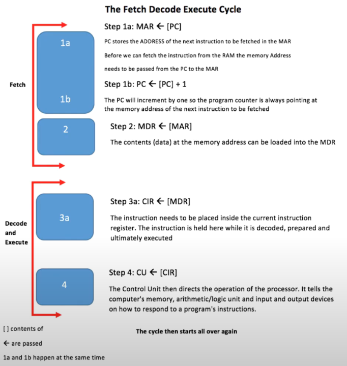
Fetch Stage
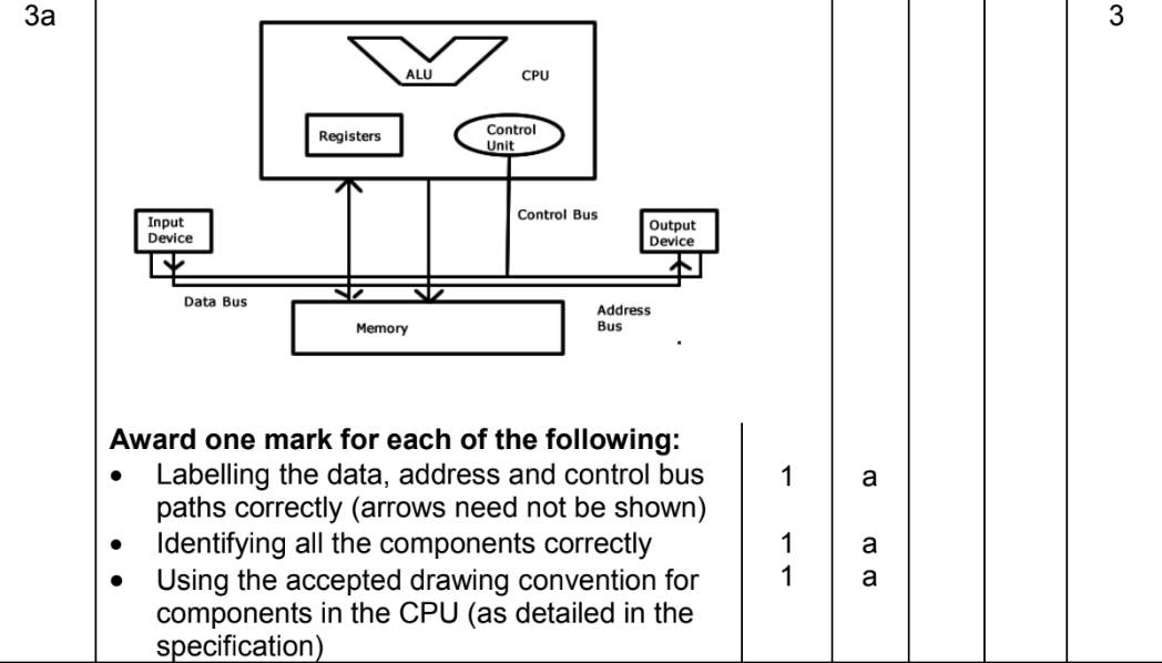
- The program counter (PC) keeps the address of the next instruction to be executed. The contents of the PC are copied to the memory address register (MAR), which is connected to the address bus. The address of the next instruction to be executed is placed on the address bus.
- Once the address of the instruction is on the address bus, the control unit instructs a memory read operation to allow the contents of the memory location to be transferred to the processor. The instruction that is stored at that address is transferred using the data bus from the main memory to the processor, and is saved in the memory buffer register (MBR)/memory data register (MDR). Simultaneously, the contents of the program counter (PC) are incremented by one so that they point to the address of the next instruction that needs to be fetched.
- The contents of the memory buffer register (MBR)/memory data register (MDR) are copied to the current instruction register (CIR). This ensures that the current instruction is kept safe so that the memory buffer register (MBR)/memory data register (MDR) can be used during the execute stage, in order to store additional data that is needed.
Decode Stage
1. The control unit decodes the instruction that is kept in the current instruction register (CIR). This involves splitting the instruction into operand and opcode to determine what type of instruction needs to be carried out, checking if additional data are required from memory, and figuring out where these are kept in main memory.
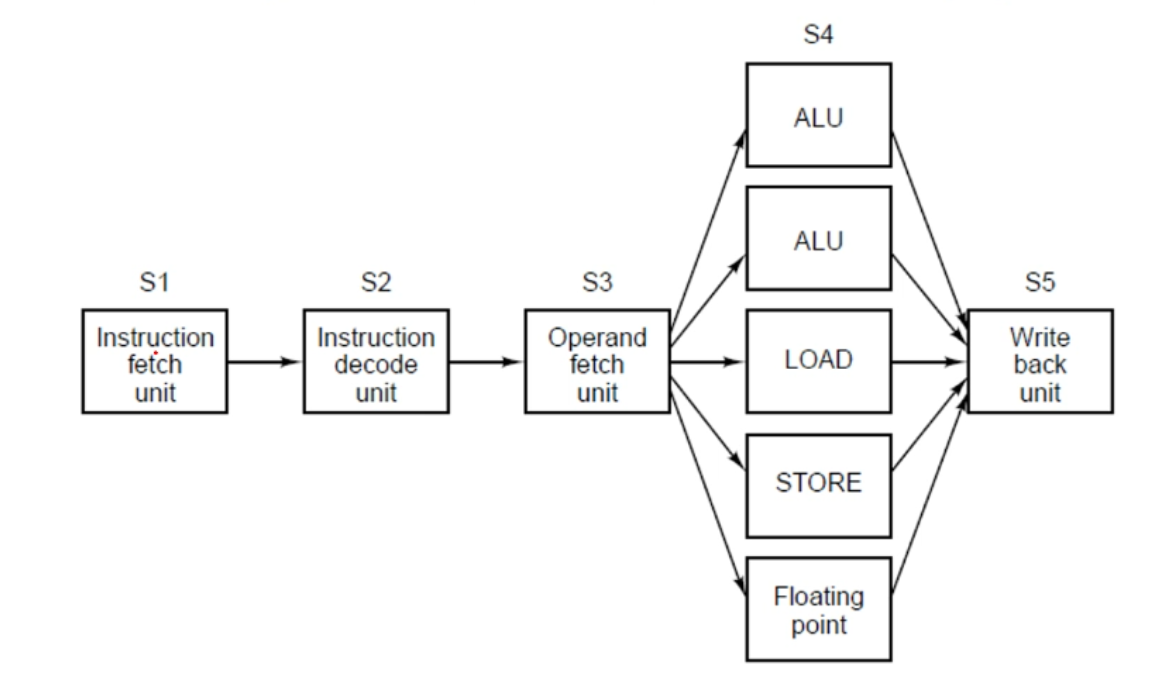
Execute Stage
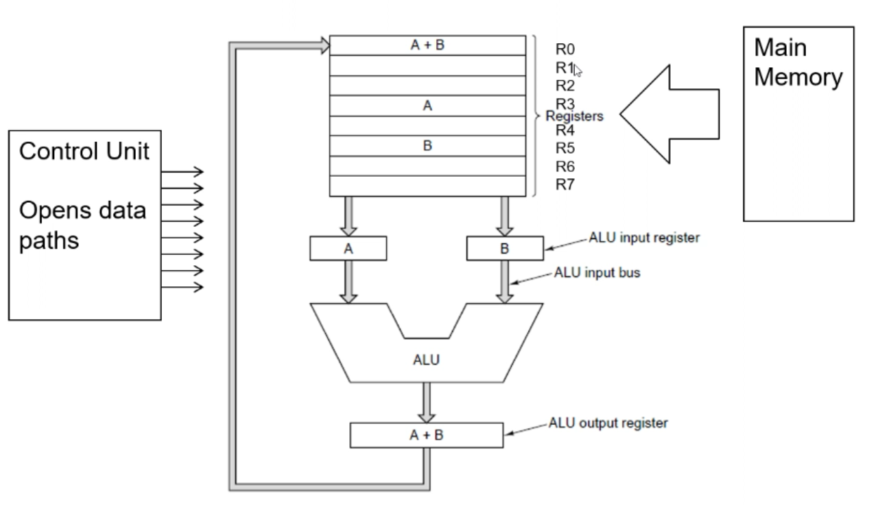
- The instruction is executed. The exact sequence of operations depends on the type of instruction that is being executed. For example, for an arithmetic instruction (such as adding two numbers together) any required data are fetched from the main memory, then the calculation is executed by the Arithmetic and Logic Unit (ALU), and the result of the instruction is stored in the accumulator, a general-purpose register, or back into main memory.
- In case the program requires a non-sequential instruction to be executed, for example if the current instruction is a branch at this stage, the address of the next instruction to be executed is determined and loaded to the program counter (PC).